
Learning how to check continuity with a multimeter is one of the most practical skills you can pick up in your workshop. Whether you’re troubleshooting a dead circuit, testing a suspect wire, or verifying that a switch actually works, continuity testing saves you hours of frustrating guesswork. It’s faster than replacing parts randomly, cheaper than calling an electrician, and honestly, it feels pretty satisfying when you nail the diagnosis.
The good news? It’s dead simple once you know what you’re doing. In this guide, I’ll walk you through exactly how to use your multimeter to test continuity like a pro, plus show you the common mistakes that trip people up.
Table of Contents
What Is Continuity Testing?
Continuity is just a fancy way of saying “is there an unbroken path for electricity to flow?” When you test continuity with a multimeter, you’re checking whether current can travel from point A to point B without any breaks, bad connections, or blown components in between.
Think of it like testing a garden hose. If water flows freely from one end to the other, you’ve got continuity. If there’s a crack or kink blocking the flow, you don’t. Same principle applies to electrical circuits.
This is different from measuring voltage or resistance in other ways—continuity testing specifically tells you yes or no: “Can electricity get through this or not?” Your multimeter does this by sending a tiny current through the circuit and listening for it to come back. If it hears that beep (on most multimeters), you’ve got continuity. No beep? Something’s broken.
Understanding Your Multimeter
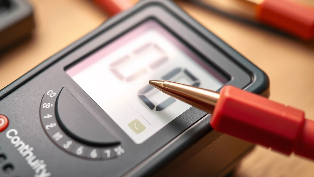
Before you start testing, you need to get familiar with your tool. Most digital multimeters have a dial in the center with different measurement modes around the edge. You’re looking for the continuity symbol—it usually looks like a little sound wave or the Greek letter omega (Ω), sometimes labeled as “Continuity” or marked with a beep icon.
Analog multimeters (the old needle-style ones) work too, but digital multimeters are way easier for beginners because they literally beep at you when continuity exists. No guessing required. Some fancier models have a dedicated continuity button instead of a dial setting.
Your multimeter also has two probes: a red one (positive) and a black one (negative). For continuity testing, polarity doesn’t matter—you can swap them around and get the same result. The multimeter is just checking if a complete circuit exists, not measuring direction.
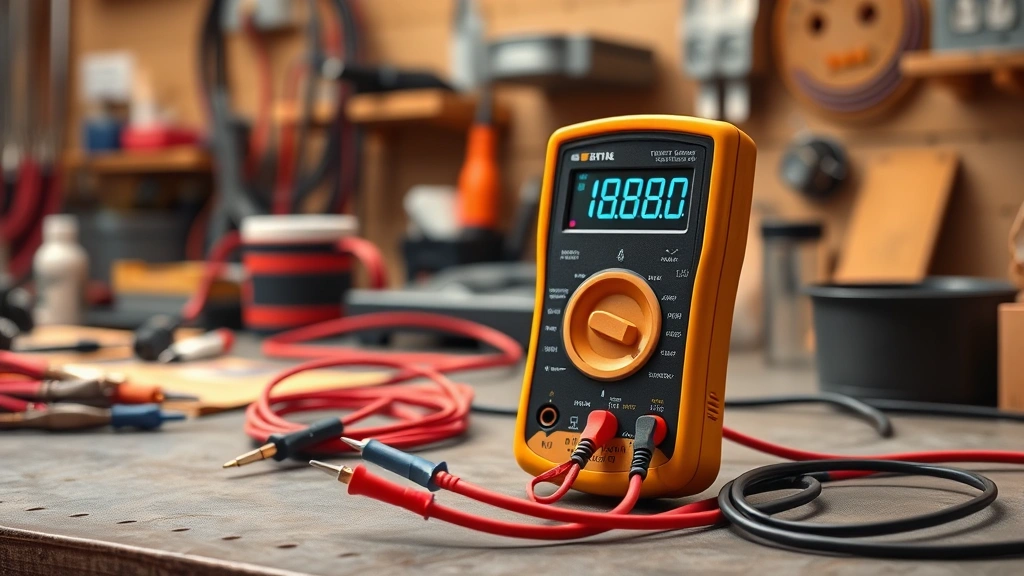
Preparing Your Multimeter
Here’s where people mess up most often: they skip the setup. Don’t be that person. First, make sure your multimeter has fresh batteries. A weak battery can give you false results. Check the battery compartment—most multimeters use standard AA or 9V batteries.
Next, insert your probes firmly into the correct jacks. The black probe goes in the COM (common) jack. The red probe goes in the appropriate jack for your test—usually marked with a Ω symbol or VΩmA. If you’re unsure, check your multimeter’s manual. It takes thirty seconds and saves you from damaging your tool.
Now rotate the dial to the continuity setting. You’ll know you’re in the right spot when you see the continuity symbol. Some multimeters beep when you first select continuity mode as a test. That’s normal—it’s just saying “I’m ready to work.”
Five Essential Steps to Test Continuity
Step 1: Power Down Everything
This is non-negotiable. Turn off power to whatever circuit you’re testing. Unplug devices, flip breakers, remove batteries—whatever applies. Testing continuity on a live circuit is dangerous and can damage your multimeter. You’re sending a tiny current through your test circuit, and you don’t want that interfering with actual power flowing through.
Step 2: Identify Your Test Points
Before touching anything with your probes, figure out exactly where you’re testing. Are you checking a wire? Test from one end to the other. Testing a switch? One probe goes on each terminal. Testing a component? Same deal—probe goes on each connection point. Write it down if you need to. This prevents you from testing the wrong thing and wasting time.
Step 3: Touch Your First Probe
Take your black probe and place it firmly on the first test point. You want good contact—press it against the metal, don’t just barely touch it. If you’re testing a wire, strip a tiny bit of insulation first so the probe makes contact with bare copper. This is where a lot of people get false negatives because they’re not making solid contact.
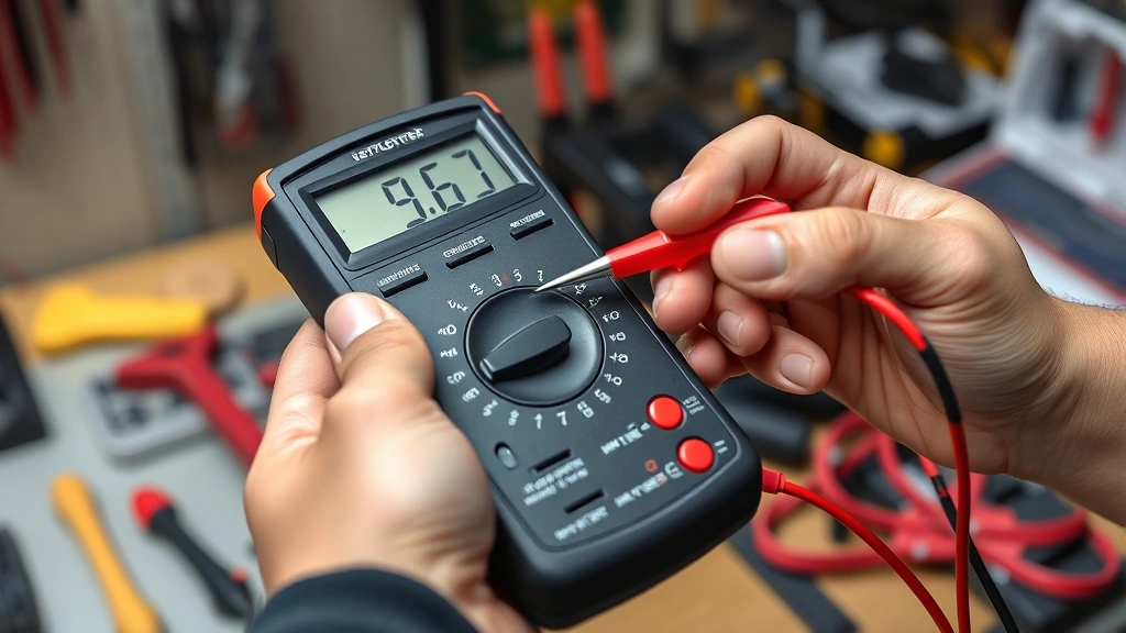
Step 4: Touch Your Second Probe
Now take the red probe and place it on the second test point with the same firm pressure. Hold both probes steady for a second. Your multimeter will either beep (continuity exists) or stay silent (no continuity). Some models show a reading on the screen too—usually “0” or “OL” (overload). The beep is your main indicator though.
Step 5: Record Your Result
Write down what you found: continuity or no continuity, and what you were testing. This matters more than you think, especially if you’re troubleshooting a complex circuit. You’ll want to remember which wire tested good and which one didn’t.
Common Testing Mistakes to Avoid
The biggest mistake is testing a live circuit. Seriously, turn off the power first. Your multimeter isn’t designed to handle full circuit voltage in continuity mode, and you could get hurt.
Second mistake: bad probe contact. If your probe is just touching paint, corrosion, or insulation instead of bare metal, you’ll get a false “no continuity” reading even though the circuit is actually fine. Always strip insulation or clean off corrosion before testing.
Third: testing the wrong thing. I’ve seen people test from a wire to ground instead of from one end of the wire to the other. Know what you’re actually trying to verify before you start poking around. Check out our Fix How To guide for more troubleshooting fundamentals.
Fourth: not understanding what you’re testing. A switch in the “off” position should show no continuity. A switch in the “on” position should beep. A broken wire shows no continuity. A good wire shows continuity. Know what the expected result should be before you test.
When to Test Continuity
Continuity testing is your go-to for several common situations. Testing a suspect wire is the classic use—if you think a wire is broken inside its insulation, continuity testing tells you instantly. Testing switches works great too; a bad switch won’t beep when it’s supposed to.
You can also test fuses, connections, and solder joints. If you’re building something electronic or troubleshooting an appliance, continuity testing helps you verify that all your connections are actually connected. It’s also useful for tracing wires in a harness or figuring out which terminal does what.
People often use continuity testing when working on automotive projects. You can verify that a ground wire actually goes to ground, or that a switch is making proper contact. Same applies to any electrical system—HVAC, lighting, power tools, you name it.
Safety Considerations Matter
Always turn off power before testing. This protects you and your multimeter. If you’re testing something battery-powered, remove the battery. If it’s plugged in, unplug it. If it’s on a circuit breaker, flip the breaker. No exceptions.
Wear safety glasses if you’re working on anything that could spark or have debris. Keep your multimeter away from moisture—don’t test in wet conditions. If your multimeter gets wet, let it dry completely before using it again.
Never test a capacitor with continuity mode while it’s still charged. Capacitors can hold a charge even when power is off, and that charge can damage your multimeter or hurt you. Discharge the capacitor safely first using an insulated screwdriver across its terminals.
If you’re working on high-voltage equipment like a microwave or CRT monitor, get professional help. Those devices have dangerous voltages that can kill you even when unplugged. Continuity testing is for low-voltage circuits and simple troubleshooting.
Interpreting Your Results
A beep means continuity exists. The circuit is complete, current can flow, and that part is probably fine. If you were testing a wire, it’s not broken. If you were testing a switch in the on position, it’s making contact properly.
No beep means no continuity. There’s a break somewhere in the path you tested. Could be a broken wire, a bad connection, a blown fuse, or a failed component. Now you know where to focus your troubleshooting.
Some multimeters show a resistance reading instead of just beeping. Zero ohms (or very close to it) means continuity. Infinite ohms (shown as “OL”) means no continuity. Most digital multimeters do both—they beep AND show the reading, which is helpful.
If you get an unexpected result, test again. Make sure your probes are making good contact. Try testing something you know is good (like a copper wire) to verify your multimeter is working. Then go back and retest your original circuit. Sometimes a dirty connection or loose probe gives you a false reading.
Frequently Asked Questions
Can I test continuity on a live circuit?
No. Always turn off power before testing continuity. Testing a live circuit can damage your multimeter and injure you. The multimeter’s continuity mode uses a small internal battery to send a test current, and it’s not designed to handle actual circuit voltage.
Why doesn’t my multimeter beep when I test?
Most likely your probes aren’t making good contact with the test points. Make sure you’re pressing firmly on bare metal, not paint or insulation. Also verify you’ve selected the continuity setting on your dial. Some multimeters require you to press a button to enable the beep feature.
What’s the difference between continuity and resistance testing?
Continuity testing just tells you yes or no—is there a complete path? Resistance testing measures exactly how much resistance exists in ohms. For simple troubleshooting, continuity is faster and easier. For precise electrical work, you might need resistance measurements instead.
Can I test continuity on a circuit board?
Yes, but be careful. Use gentle pressure with your probes to avoid damaging tiny components or solder joints. Test from one solder pad to another, or from a component lead to a trace. Make sure the board is powered down first. For detailed electronics work, you might want a multimeter with finer probe tips.
How do I know if my multimeter is working correctly?
Test it on something you know is good. Take two probes and touch them together—you should get a beep and a very low resistance reading (close to zero). If that works, your multimeter is functioning. If it doesn’t beep when the probes touch, check your batteries and probe connections.